FC-T12 2-axis gimbal assembly and bench test.
Unit overview
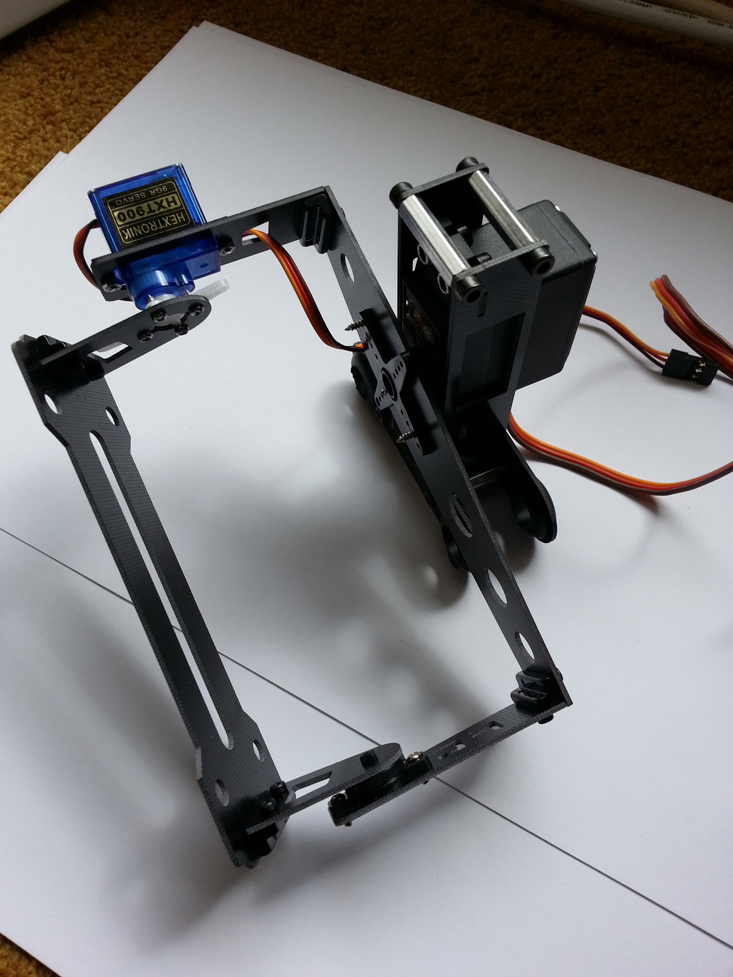
FC-T12 2-axis gimbal from HobbyKing is a cheap ($15US) and light (72g without servos – 124g all up in this configuration) 2-axis gimbal suitable for small cameras.
In this build configuration, the servo controlling pitch is a Hextronik HXT900 9gr / 1.6kg / 0.12sec micro. The servo controlling roll is a Hextronik 5010 39.2g / 6.9kg / 0.16sec standard servo. The controller is a OpenPilot Revolution, purchased via the OpenPilot store and configured as per the OpenPilot Wiki article on Camera Stabilization Configuration.
Benchtest
Assembly
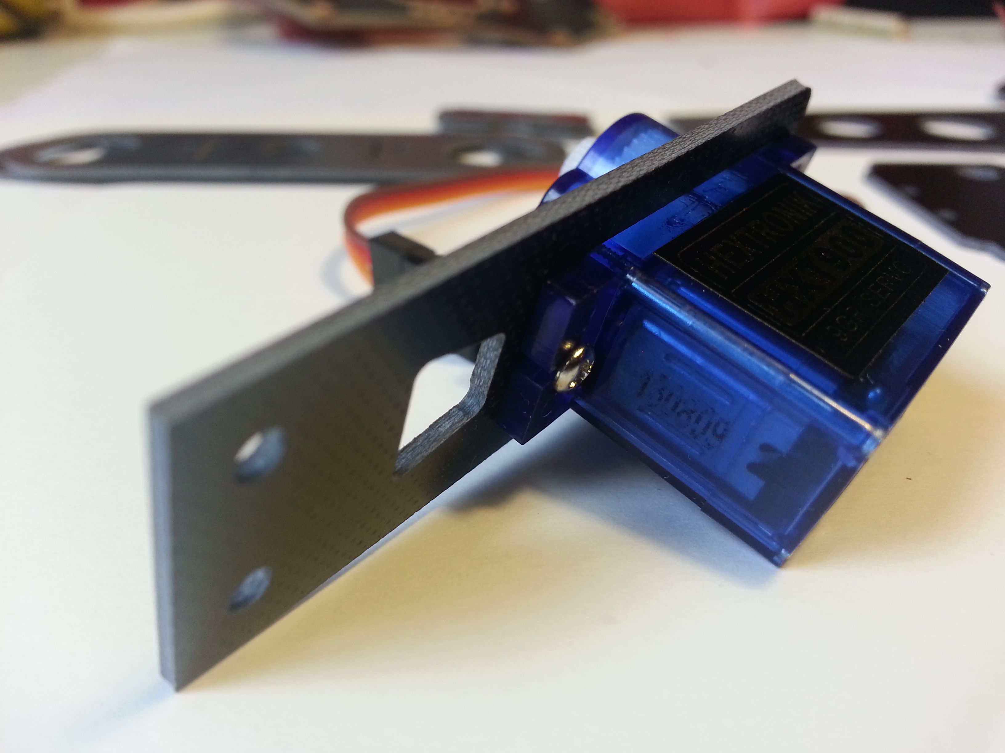
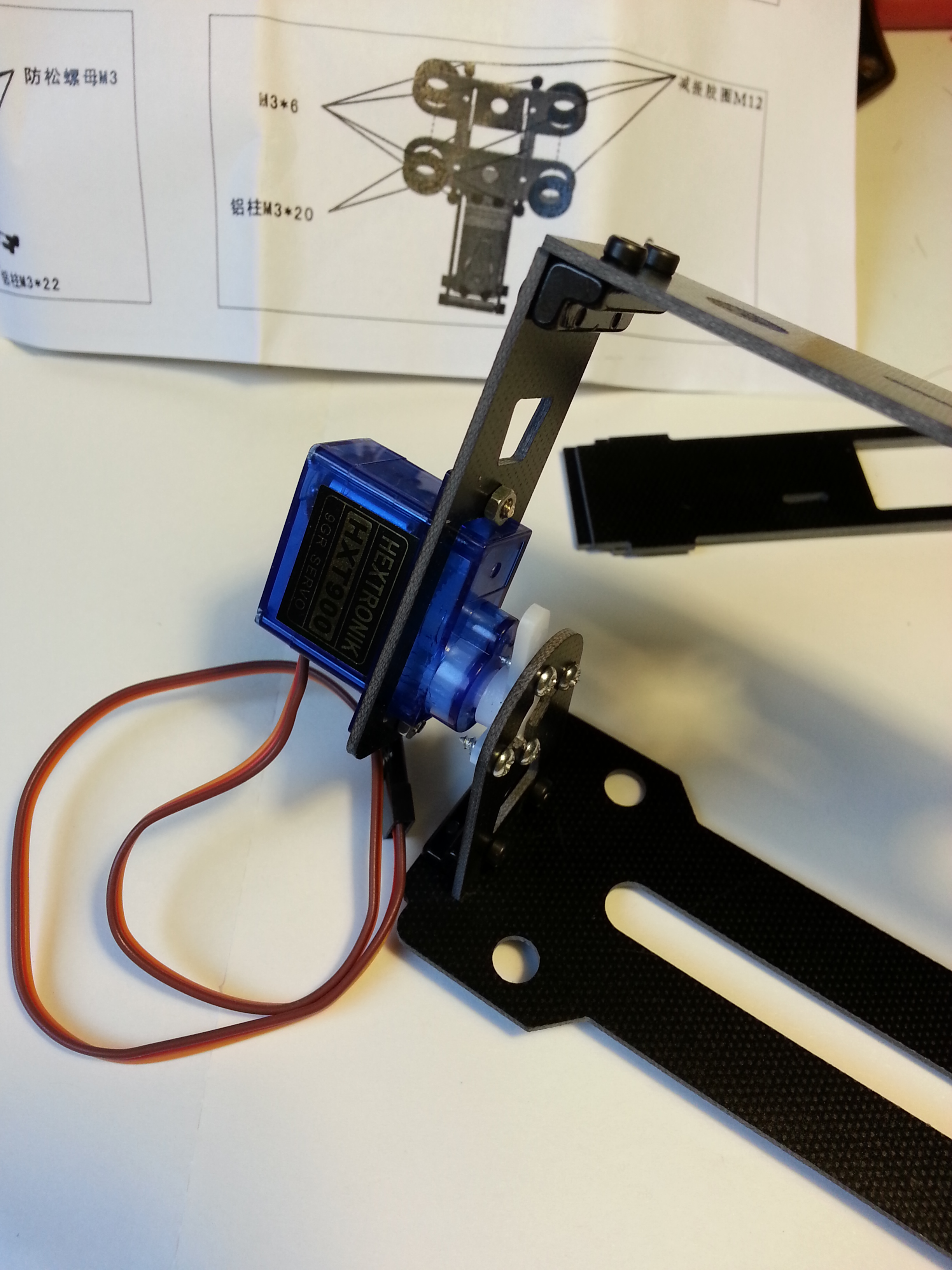
Attach the micro servo to the first plate.
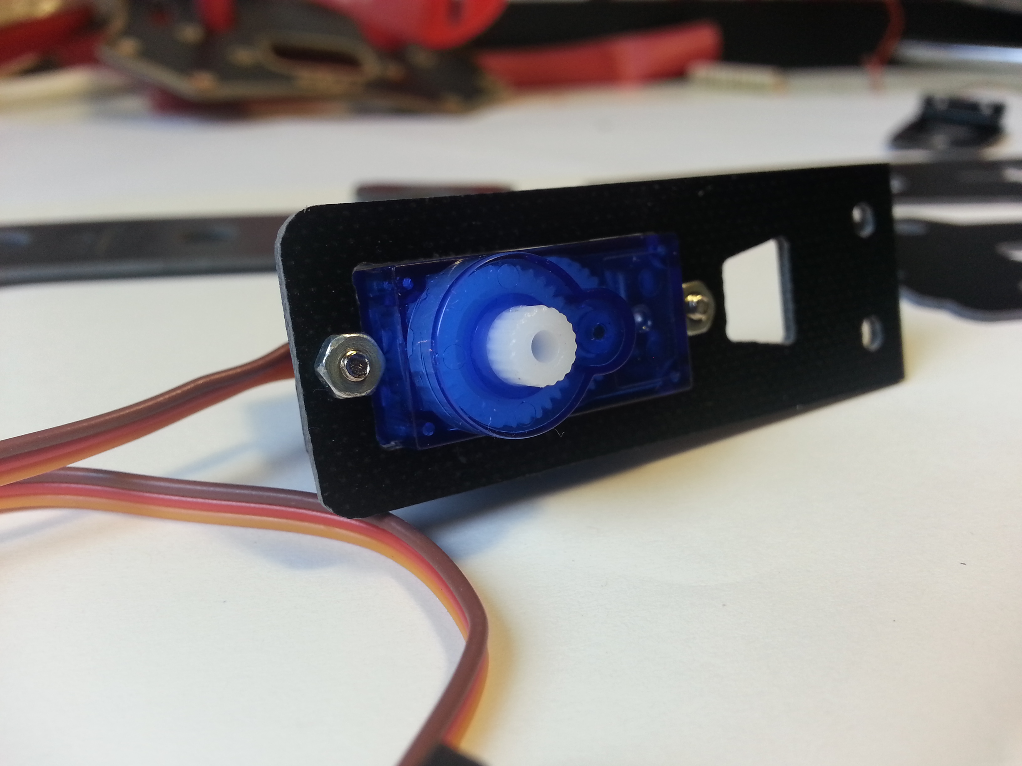
The screws in position:
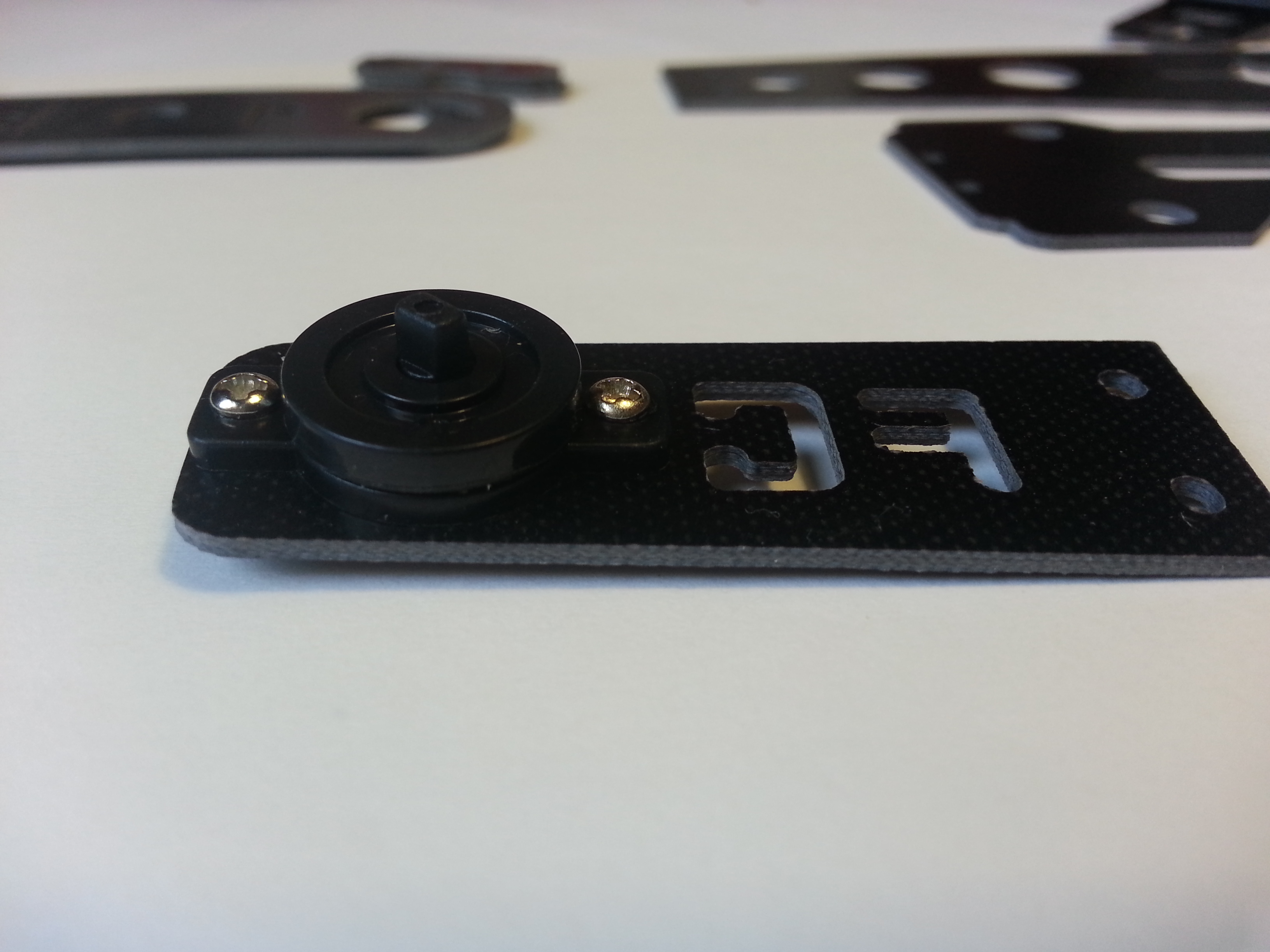
Prepare the counterpart plate with turntable.
Connect right angle fillets to the arms.

Then the arms to the bridging plate.
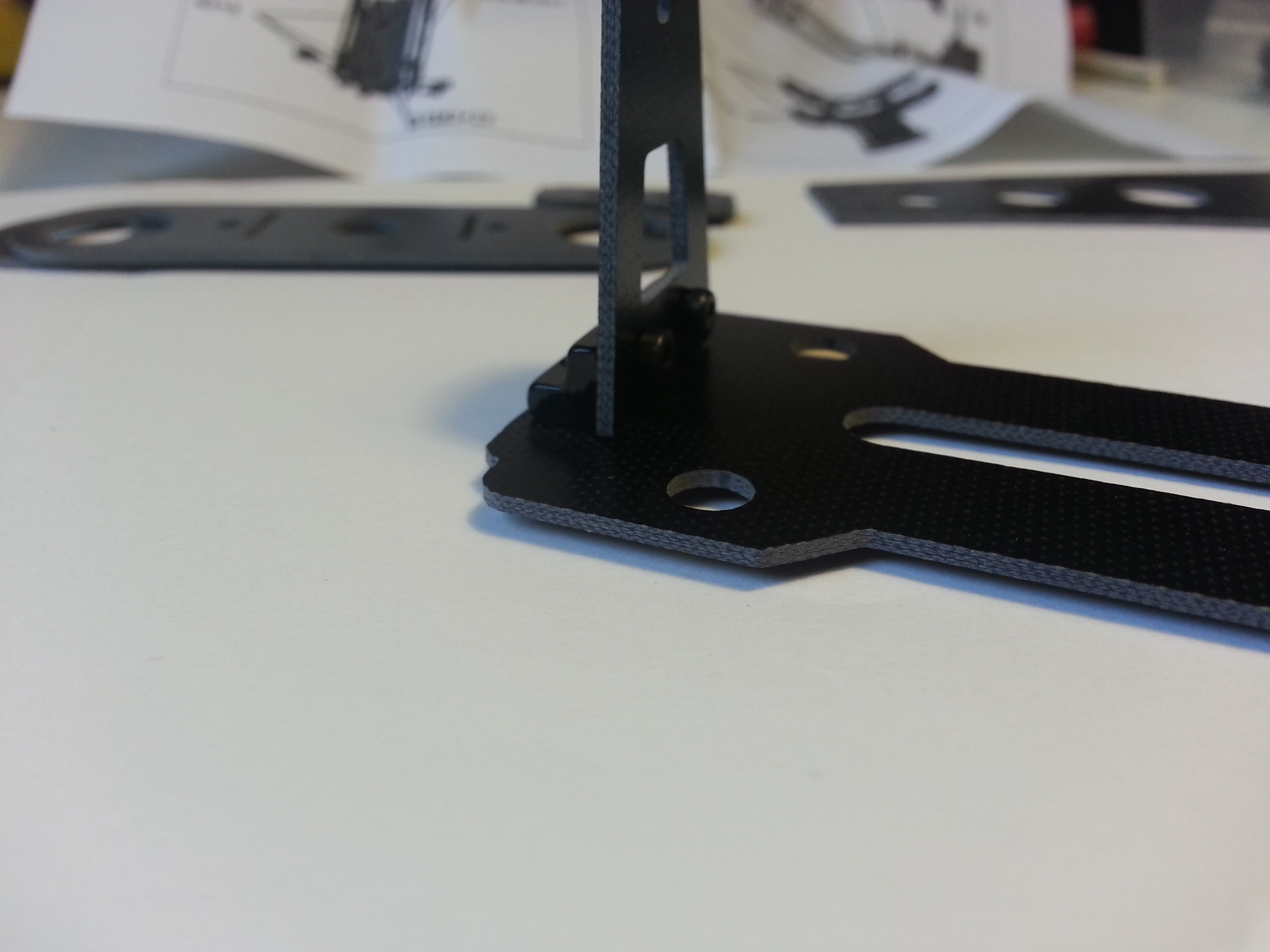
Then attach the camera baseplate.
At which point you can commence the main attachment of the gimbal.
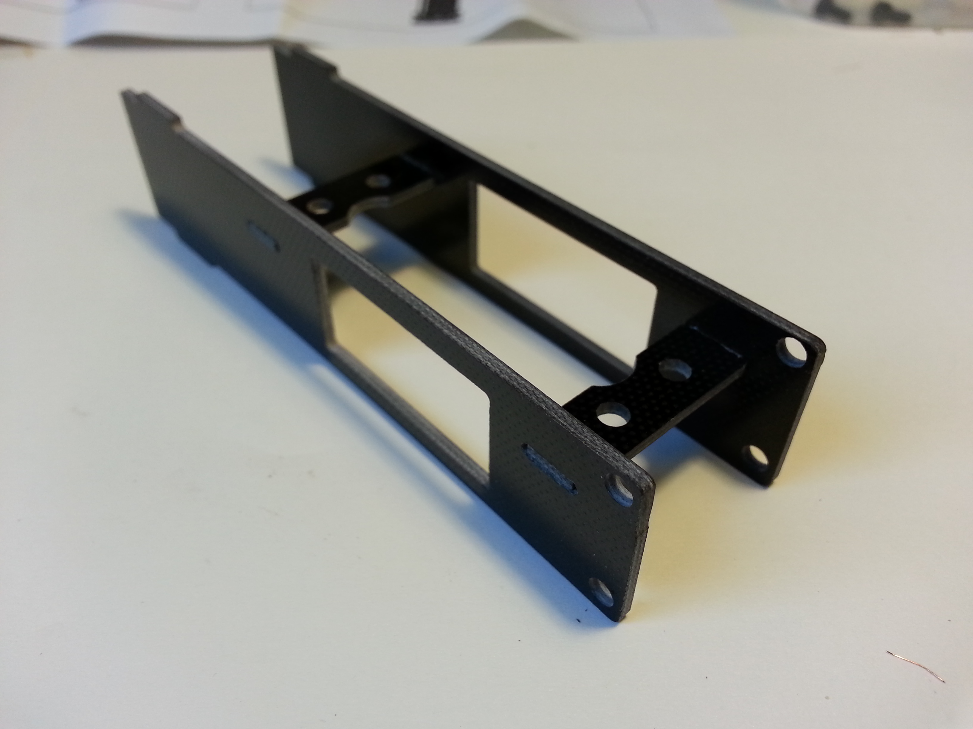
The prepared connector plate.

One half of the connector plate in place.

The other half in place.

Support braces in place.
Standard servo in place.
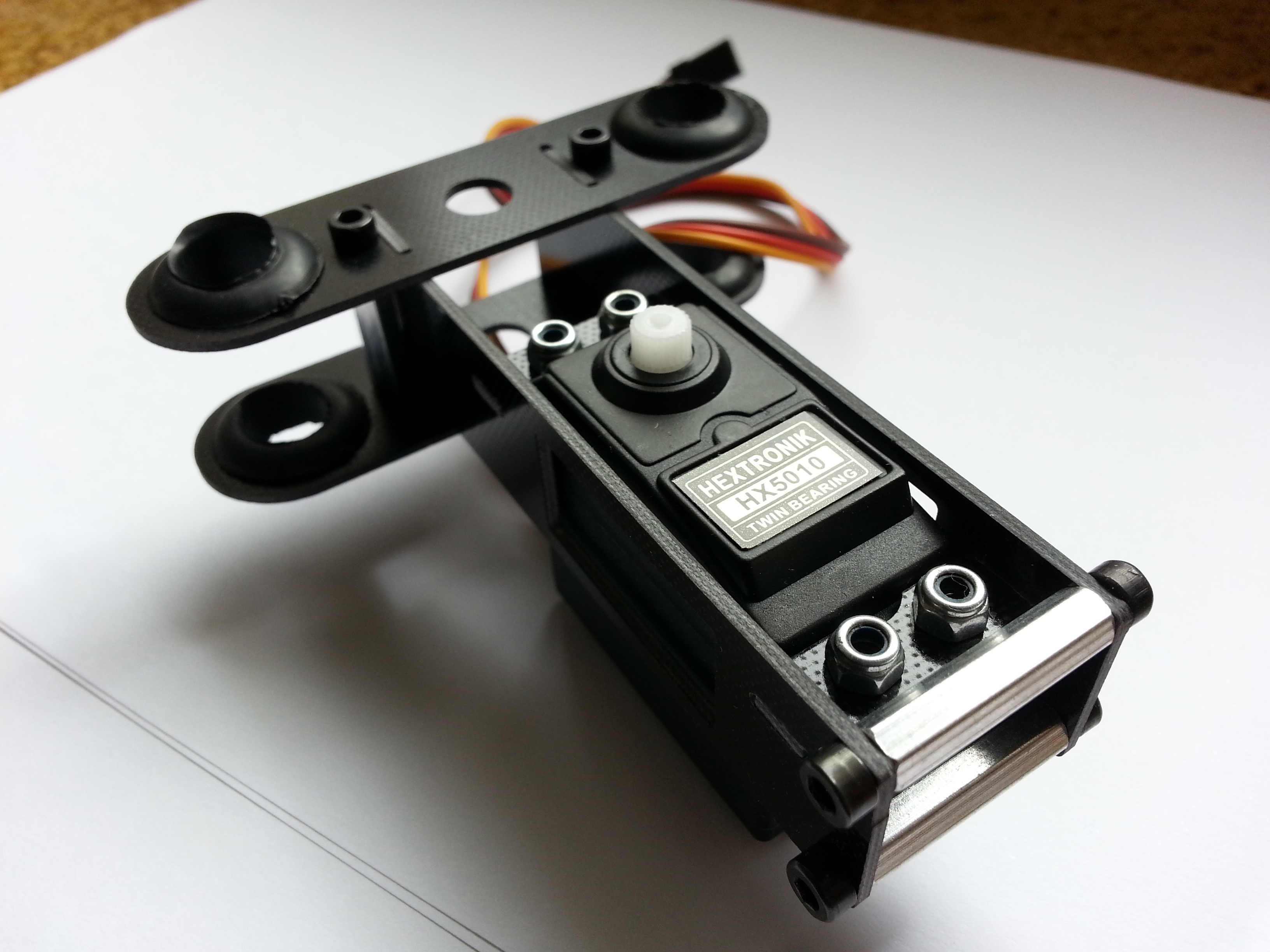
The thread is only just long enough for the nuts to engage.
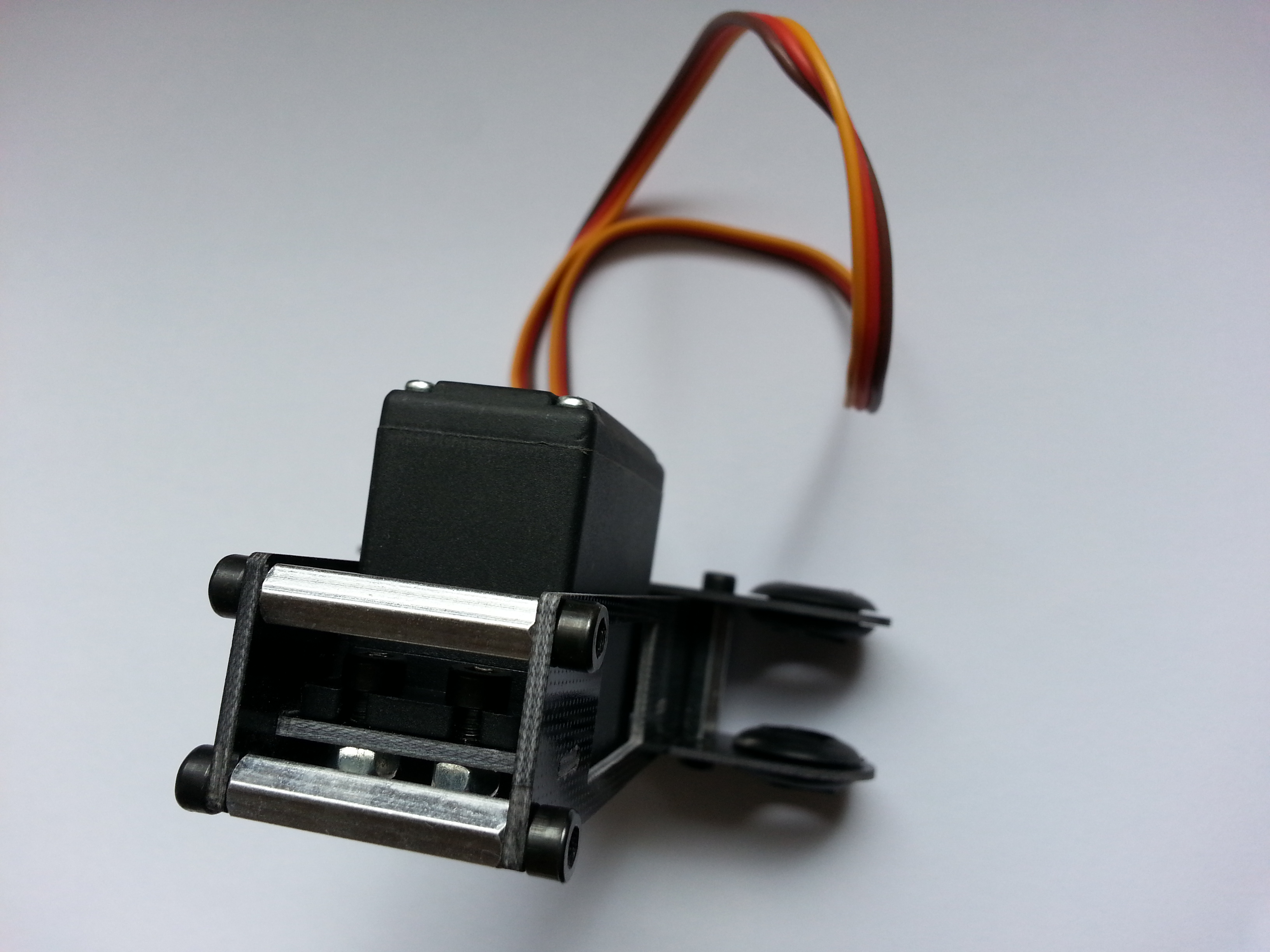
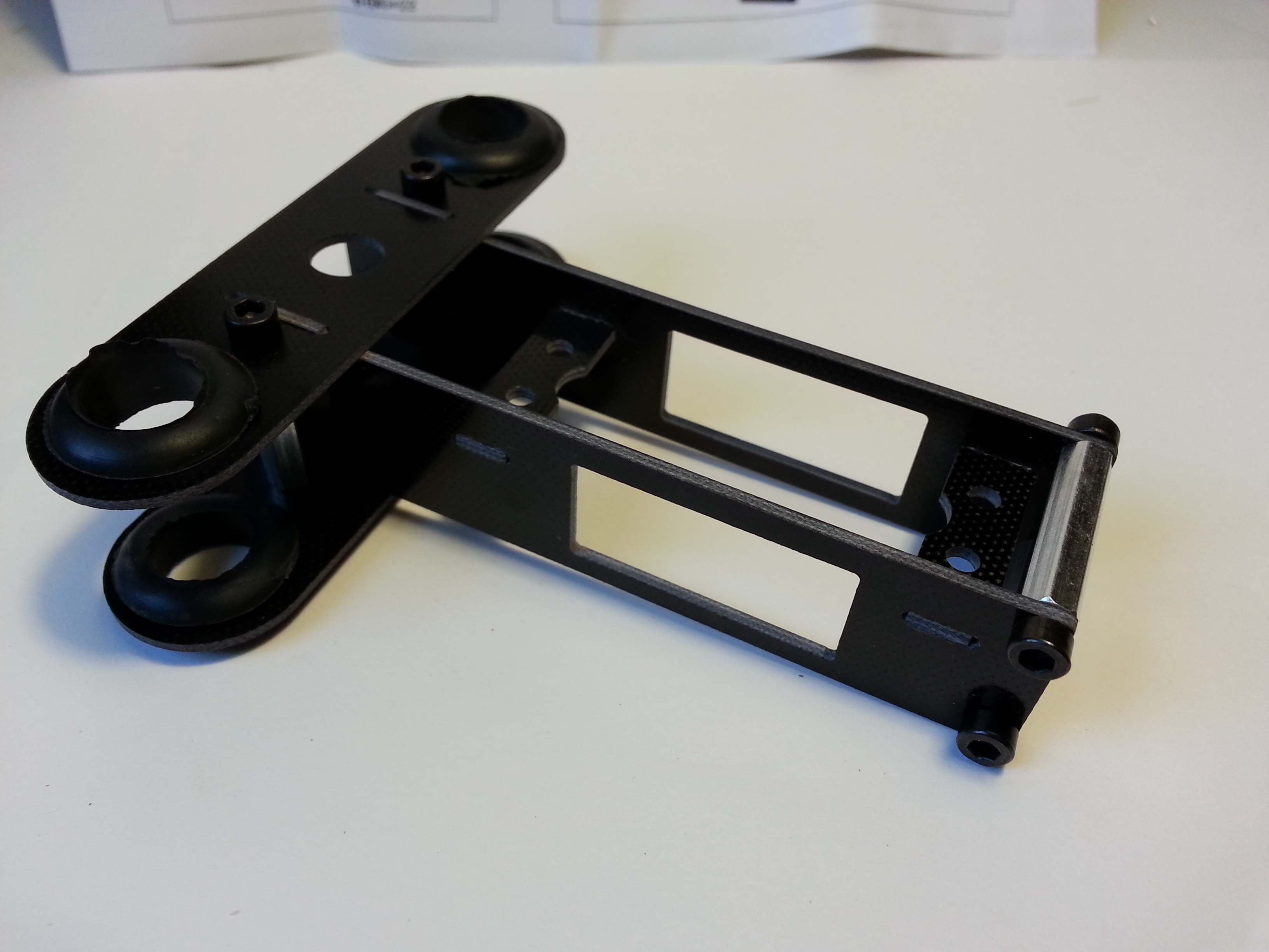
Couple the two halves.
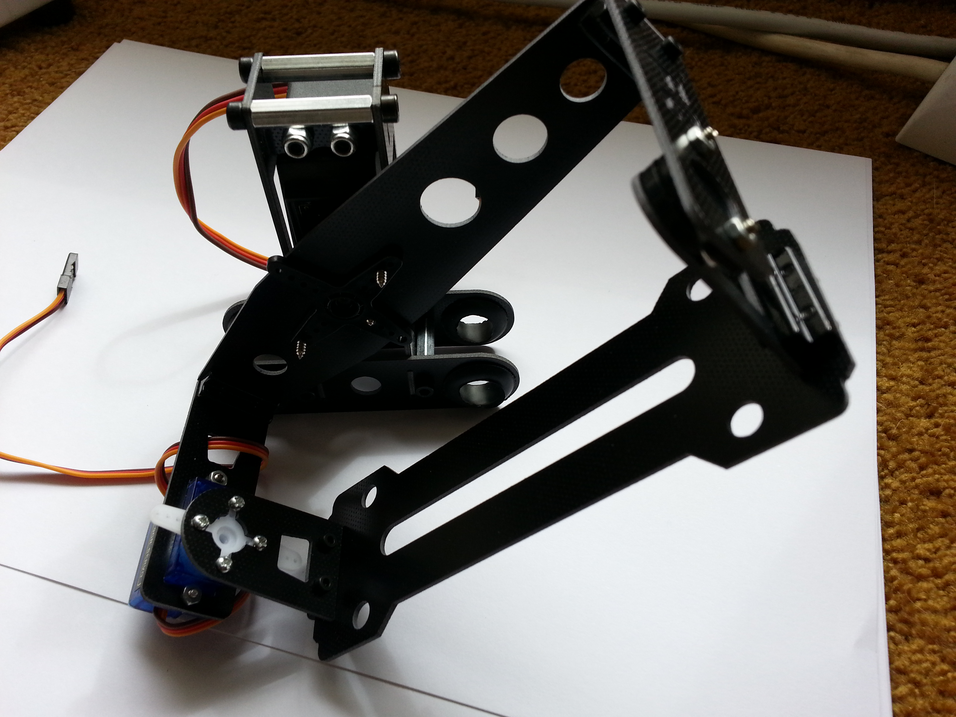
The assembled unit.